Rugged connectors and the power of high-speed communication protocols
By Jean-Marie Buchilly, new product development manager, Fischer Connectors
Electronics Interconnect Supply Chain communication communication protocols connector connector protocols rugged ruggedNo one has to tell an engineer that modern equipment demands high-speed data transfer. However, making sure those high speeds are maintained continues to challenge the best of us. It makes sense that engineers look closely at all components, including cables and connectors, when they need to deliver data at top speeds throughout their system.
This article provides an overview of the most relevant parameters that determine whether a connector and/or cable assembly can deliver the speed of your selected protocol. Selecting the right protocol for a new digital system or technology requires consultation with a reputable connectivity supplier that can help the design team make the right decisions.
So what does a ╥communication protocol╙ actually define? It is a system of digital message formats and rules for exchanging messages in, or between, computing systems or in telecommunications. Communication protocols can include signaling, authentication, and error detection and correction capabilities. A protocol can be implemented as hardware, software or both. The systems designers and component suppliers must agree upon the relevant communication protocols in order to ensure proper performance and operation of the new technology.
Communication Protocol IEC 11801
International standard ISO/IEC 11801 specifies general-purpose telecommunications cabling systems (structured cabling) that are suitable for a wide range of applications╤analog and ISDN telephony, various data communication standards, building control systems, factory automation, etc. The standard defines several link/channel classes and cabling categories of twisted-pair copper interconnects, which differ in the maximum frequency for which a certain channel performance is required.
There is a set of parameters available within the IEC 11801 standard that help define balanced cabling performance. The most relevant are listed below.

Fig: 1A
Insertion Loss (IL)
Insertion Loss, or attenuation, is the reduction in amplitude of a transmitted signal in a wire pair as a function of the frequency.
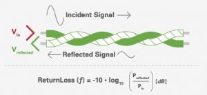
Fig 1B
Return Loss (RL)
Return Loss is the measurement of the intensity of the reflected signal in a wire pair (measured on the same side of the cable from where the signal is emitted). The signal reflection is due to impedance mismatches (usually caused by manufacturing defaults).

Fig 1C
Near End Crosstalk (NEXT)
Near End Crosstalk (NEXT) is the ratio of the amplitude of the transmitted interference and the amplitude of the signal creating this interference applied on another wire pair, measured on the same side of the cable from where the signal is emitted.

Fig 1D
Far End Crosstalk (FEXT)
Far End Crosstalk (FEXT) is the ration of the amplitude of the interference transmitted and the amplitude of the signal creating this interference applied on another wire pair. The transmitted interference is measured on the other side of the cable from where the signal is emitted.
Components category and balanced cabling performances
According to the ISO/IEC standards, structured cabling components (e.g. cables, connecting hardware, and patch cords) are characterized by a performance ╥category╙, and are mated to form a permanent link or channel that is described by a performance ╥class╙╤in Telecommunications Industry Association (TIA) Standards, components and cabling are both characterized by a performance ╥category╙.
ISO/IEC 11801 defines the following correspondences between component category and balanced cabling performance class:
* Category 5 components provide Class D balanced cabling performance;
* Category 6 components provide Class E balanced cabling performance;
* Category 6A components provide Class EA balanced cabling performance;
* Category 7 components provide Class F balanced cabling performance;
* Category 7A components provide Class FA balanced cabling performance.
*ISO/IEC 11801 defines what performances have to be achieved within the frequency range for all classes. ISO/IEC 11801 also defines the balanced cabling class that is recommended for the type of application.
Here’s a practical example of how these classes can be applied to a system design. You need Category 5 (Cat. 5) components to produce a Class D balanced cabling that can be used for Ethernet 1000base-T applications (Gigabit Ethernet, IEEE 802.3ab).
A manufacturer should also consider that the USB 2.0 protocol is less severe and only requires a minimum Insertion Loss value in the 0-400MHz frequency range. Other common parameters, such as Return Loss, Near End Crosstalk and Far End Crosstalk, are not specified in the USB 2.0 Specifications. The USB 2.0 standard is capable of transfer rates as high as 480 megabits per second (mbps), or 60 megabytes per second (MBps). The newer USB 3.0 protocol can, by comparison, handle transfer data rates up to 5 gbps (640 MBps). This makes it ten times as fast as the USB 2.0 maximum.
Design rules and simulation
Designing a connectivity solution for a specific data protocol requires optimizing the design of both the connector and the cable. The first condition for a functional solution is to have a connector that is capable of handling the specified communication protocol.
Each protocol requires specific design rules for the connector. All of these specific rules are combined for multi-protocol connectors. Software simulation is the perfect tool for this design process, since it allows the designer to check the compatibility of the designed connector/cable assembly with the targeted protocol. The effects of design modifications can immediately be evaluated in time and in the frequency domain, which enables an optimized design with a high confidence level that the connector will perfectly match the desired protocols.
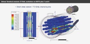
Fig 2
Characterization and qualification
Once the design has been optimized for a defined protocol, a physical product prototype needs to be tested. This testing is a critical step in designing and developing a quality connectivity solution for a new technology. Without the testing, a manufacturer could have costly issues during production, or could face failures in the field.
S-parameters of the cable assembly are measured and compared with the target values defined in the protocol specification (e.g. USB 3.0, HDMI, Ethernet). If one of the parameters fails, an iteration loop will be made on the design until the cable assembly fulfills all protocol requirements. At this time, the product can be declared ‘protocol compatible’.
When it is critical that a connector solution achieves a certain speed such as USB 3.0 (5 Gbit/sec), designers should work with their connector suppliers to get specific cable recommendations. It will save the trial and error that the supplier should have already gone through to find the solutions that will work best for a manufacturer’s application.
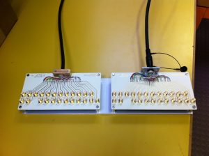
Fig 3
Summary
Understanding the impact a connectivity solution has on communication protocols allows you to build a more robust solution. You can avoid the ╥data bottleneck╙ by approaching this challenge early in your design cycle. The goal is to build a system that performs flawlessly and transparently through the lifecycle of its application. Take a close look at your connectors and connectivity solution, test prototypes thoroughly with a professional organization, and move forward with confidence.